
























Stop Outdoor Coil Icing: Finding the Right Heat Pump Defrost Control Board Replacement for Winter
Share
HVAC SUPPLIES
Heating System Maintenance Guide
Heat Pump Defrost Control Board Diagnostic and Replacement Guide
Picture stepping outside on a freezing morning, heading over to your HVAC system, and discovering your outdoor unit encased in a solid, unforgiving block of ice while the indoor registers blow ice-cold air into your living room. When autumn freeze-thaw cycles settle in, a light coating of frost on the exterior coils is completely standard behavior for a modern heat pump. However, when that frost accumulates continuously until the entire heat pump turns into a solid iceberg, you are facing a critical component breakdown within the defrost control loop. Left unaddressed, persistent ice buildup chokes off airflow through the outdoor coil, lowers refrigerant pressure, and eventually forces unevaporated liquid refrigerant back into the compressor pump. This phenomenon, known as liquid slugging, can cause catastrophic compressor burnout, turning a simple repair into a multi-thousand-dollar system overhaul. Performing a timely heat pump defrost control board replacement is often the single most effective way to restore proper operation, protect your investment, and ensure consistent indoor warmth throughout the coldest months of the year.
Diagnosing a frozen outdoor coil requires understanding how a system balances heating demand with thermal maintenance. For homeowners, property managers, and field technicians looking to source reliable replacement components, having access to exact-fit HVAC inventory makes all the difference. You can explore an extensive range of replacement parts, heat pumps, and multi-zone climate solutions at HVAC Supplies to find reliable hardware tailored to your specific system configuration. When winter weather hits hard, having a clear diagnostic roadmap allows you to isolate the failure quickly and restore your heating system to peak performance without unnecessary downtime.
Understanding the Defrost Cycle and Why Boards Fail
To understand why a heat pump freezes up, it helps to review how a healthy heat pump manages frost accumulation during normal winter operation. When running in heating mode, the outdoor coil acts as an evaporator, extracting heat energy from the surrounding cold outdoor air. As moisture in the atmosphere contacts the frigid coil fins, frost naturally forms on the metal surfaces. To clear this frost, the heat pump periodically switches its operating state into defrost mode. During a defrost cycle, the defrost control board energizes the reversing valve to temporarily flip the system into cooling mode. This redirects hot discharge gas from the compressor directly into the outdoor coil, melting away accumulated ice within minutes. Simultaneously, the control board turns off the outdoor condenser fan to preserve heat within the cabinet and engages indoor auxiliary heat strips to keep cold air from blowing into the living space.
The entire defrost sequence relies on a coordinated effort between an outdoor coil temperature sensor, ambient thermal sensors, internal timer logic, and electromechanical relays mounted on the defrost board. When any of these electronic components degrade, the board fails to initiate or terminate the defrost process. Signs of defrost control board failure usually manifest in three primary ways:
1. Persistent Ice Buildup: The outdoor unit remains completely iced over even during relatively mild, humid winter days, or it fails to clear itself after manual diagnostic testing.
2. Perpetual Defrost Loops: The system gets stuck in a perpetual loop where the defrost cycle either never initiates at all, or once triggered, fails to terminate, leaving the unit stuck in defrost mode while continuously blowing cold air inside and burning electric auxiliary heat.
3. Physical or Electrical Damage: You may notice physical or audible signs of failure on the circuit board itself, such as rapid, erratic relay clicking, visible scorch marks around the terminal pins, or swollen, leaking capacitors caused by line-voltage electrical surges.
Distinguishing between a failed control board and a bad temperature sensor is an essential diagnostic step before replacing components. A faulty thermistor or defrost thermostat can mimic board failure by sending incorrect temperature signals, keeping a perfectly good board from initiating the defrost cycle. Using a digital multimeter set to measure electrical resistance (ohms), you can test the coil sensor's resistance against the manufacturer’s temperature-versus-resistance curve. If the sensor reads open, shorted, or drastically out of spec for the current coil temperature, replacing the sensor alone will solve the problem. If the sensor measures within spec but the board fails to respond when coil conditions demand defrosting, the board itself must be replaced.
Whether you are managing a single-family home or maintaining larger residential properties, keeping thermal control systems in top condition is essential for winter comfort. Homeowners seeking complete zoning solutions or supplemental heating upgrades across different regions can review localized climate options, such as San Diego, CA Mini Splits, Los Angeles, CA Mini Splits, Austin, TX Mini Splits, and Aurora, IL Mini Splits, where precise defrost management keeps heat pumps running smoothly through varying temperature swings.
Step-by-Step Diagnostic Checklist for Contractors and DIYers
Before committing to a heat pump defrost control board replacement, performing a systematic diagnostic evaluation will verify that the board is indeed the root cause of the system failure. Follow this four-step checklist to safely test and confirm board status.
Step 1: Visual Inspection & Safety First
Safety is paramount whenever working around high-voltage HVAC equipment. Begin by turning off power to the outdoor heat pump at the primary breaker panel, then pull the outdoor disconnect handle located adjacent to the condensing unit. Verify that power is completely shut off using a non-contact voltage detector or a voltmeter across the incoming line terminals. Remove the electrical panel cover on the outdoor unit and inspect the control board visually. Look closely for signs of thermal stress, burnt traces on the backside of the printed circuit board, corrosion around wiring connections, or insect nests that may have bridged high-voltage terminals.
Step 2: Check Power and Fuses
Once you have reconnected power for live testing, verify that the low-voltage control transformer is delivering the required power to the board. Place your multimeter leads across the R and C terminals on the control board to ensure you are receiving a stable 24VAC input. If 24VAC is present at the input but the board shows no diagnostic LED status lights, check for an on-board blade fuse. A blown 3-amp or 5-amp low-voltage fuse indicates a short circuit in the low-voltage wiring or a bad contactor coil, which must be resolved before powering up a new board.
Step 3: Force a Defrost Test
Most modern heat pump control boards feature dedicated diagnostic pins labeled TEST or TEST/DEFROST. To force a test cycle, bridge these two pins briefly using a flathead screwdriver or jumper wire while the system is running in heating mode. On time-temperature boards, shorting these pins bypasses the internal timer logic. If the board is functioning correctly and the defrost thermostat/sensor is closed (indicating a cold coil), you should hear the reversing valve shift with a soft swooshing sound, the outdoor fan motor should stop spinning, and the auxiliary heat circuit should energize. If shorting the test pins produces no response despite proper low-voltage input and closed sensors, the internal board logic or output relay has failed.
Step 4: Verify Sensor Resistance
Disconnect the defrost thermistor or sensor harness from the board to test its electrical integrity. Set your multimeter to the resistance scale (Ω) and measure across the sensor leads. Compare your reading against the manufacturer’s thermistor chart for the current outdoor temperature. For instance, many standard 10k-ohm sensors will read approximately 30,000 ohms at freezing temperatures 32°F. If the sensor reads infinite resistance (open circuit) or zero resistance (short circuit), replace the thermistor. If the sensor reading is completely accurate for the temperature present on the coil, but the board refuses to engage defrost, proceeding with a board replacement is necessary.
Comprehensive system maintenance across various property types often involves reviewing matched indoor and outdoor components. Property owners maintaining multi-zone or ductless heat pump setups across cold climates can browse region-specific solutions like Boston, MA Mini Splits, Buffalo, NY Mini Splits, Chicago, IL Mini Splits, Miami, FL Mini Splits, and New York City, NY Mini Splits to explore modern equipment options with built-in advanced defrost algorithms.
Choosing the Right Heat Pump Defrost Control Board Replacement
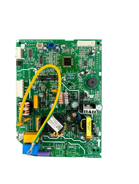
Selecting the proper replacement board requires careful attention to electrical specifications, mounting footprints, and control protocols. While Original Equipment Manufacturer (OEM) boards offer direct drop-in replacement, exact subassembly replacement boards ensure full compatibility with specific indoor and outdoor unit model series.
When replacing subassemblies, cross-referencing part numbers ensures seamless operation without needing rewiring modifications. Key exact-fit replacement boards available for specific system configurations include:
12K BTU & Compact Systems: For compact split units, the Main Control Board Subassembly 17122000044667 (KFR35G/BP3N1Y-ABB) and the Main Control Board Subassembly 17122000055270 (KFR35G/BP3N1Y-ABB) deliver reliable defrost timing and relay control for 12,000 BTU systems.
18K–24K Mid-Sized Heat Pumps: Larger residential zones operating 18,000 BTU units utilize the Main Control Board Subassembly 17122000045126 (KFR53G/BP3N1Y-ABD) or the Main Control Board Subassembly 17122000051062 (KFR51G/BP3N1Y-EPC).
24K–36K & High-Capacity Heat Pumps: For high-capacity residential and commercial mini-splits, select from options like the Main Control Board Subassembly 17122000045121 (KFR70G/BP3N1Y-ABE) or the high-output Main Control Board Subassembly 17122000051268 (KFR105G/BP3N1Y-EPD).
Low-Capacity / Single-Room Units: For smaller single-zone 9k–10k BTU applications, the Main Control Board Subassembly 17122000050501 (KFR26G/BP3N1Y-EPB) ensures proper micro-controller logic and sensor interface.
Key features to prioritize in a high-quality replacement defrost control board include:
Selectable Defrost Intervals: Look for boards that allow you to adjust field-selectable defrost cycle timing (typically 30, 60, or 90 minutes) or units equipped with demand-defrost logic that automatically adjusts cycle frequency based on actual coil conditions.
Diagnostic LED Status Indicators: Onboard diagnostic LEDs display fault codes, system status, and sensor errors directly on the circuit board, simplifying future troubleshooting.
Anti-Short Cycle Timers: Integrated compressor delay timers protect the compressor motor against rapid cycling caused by power interruptions or thermostat fluctuations.
Universal Sensor Compatibility: Ensure the replacement board supports the resistance curves of your existing coil and ambient temperature thermistors.
To avoid common compatibility traps, double-check that the board’s operating voltage matches your control system (standard 24VAC control input) and that the contactor and reversing valve relay ratings match your compressor's power draw. Mixing incompatible sensor thermistor values—such as connecting a 10k thermistor to a board programmed exclusively for 50k thermistors, will cause inaccurate temperature readings, resulting in premature defrosting or frozen coils.
If you are retrofitting or expanding a residential heat pump setup, selecting compatible indoor air handling equipment and ductless configurations is just as critical. Explore specialized cooling and heating inventory like Air Handlers, Air Handlers ACIQ, Air Handlers Cooper and Hunter, and Air Handlers MRCOOL to ensure full compatibility across your entire heating setup.
For homeowners in regions with variable coastal or mountain weather, tailored HVAC systems ensure efficient heating and cooling throughout every season. You can review localized equipment options such as Portland, OR Mini Splits, San Antonio, TX Mini Splits, Seattle, WA Mini Splits, Worcester, MA Mini Splits, San Jose, CA Mini Splits, San Francisco, CA Mini Splits, Fresno, CA Mini Splits, and Dallas, TX Mini Splits to explore how modern heat pumps operate reliably across distinct regional environments.
Installation Best Practices & Safety Precautions
Replacing a defective defrost control board is a straightforward procedure when handled with care, safety, and attention to detail. Following proper installation protocols prevents accidental damage to fragile electronic circuits and ensures long-term system reliability.
Pre-Installation Preparation
Before removing a single wire from the old board, turn off all power to the outdoor unit at the disconnect box and main panel. Take clear, well-lit photographs of the original board from multiple angles. Ensure that wire color codes, terminal labels (such as R, C, Y, O/B, W2, DFT), and plug harness orientations are fully legible in your photos. These photos will serve as an indispensable reference point when connecting the new board. Disconnect line and low-voltage wires one by one, labeling each wire with masking tape or wire markers if the original insulation color coding is unclear.
Proper Mounting and Grounding
Remove the mounting screws securing the old circuit board to the electrical control box. Handle the new replacement board by its plastic edges or standoff supports to prevent electrostatic discharge (ESD) from damaging sensitive microcontrollers. Ensure all plastic standoff pins snap securely into the electrical box backplate to prevent short circuits against the metal cabinet. Verify that the board's chassis ground terminal or mounting screw establishes a solid, clean metal-to-metal connection with the electrical enclosure. Proper grounding protects sensitive microprocessors from external voltage spikes and electrical noise.
Wire Connections & Sensor Placement
Transfer each wire connection to the corresponding terminal on the new board according to the manufacturer’s wiring schematic. Ensure that terminal screws are tightened securely and spade connectors push firmly onto terminal pins. When attaching outdoor coil thermistors, verify that the sensor bulb is mounted flush against the copper return bend near the bottom third of the outdoor coil. Apply thermal paste or clip insulation over the sensor if required by the manufacturer to guarantee accurate temperature readings.
Post-Installation Test Run
Once wiring is complete, restore power to the system and verify that board status LEDs illuminate normally. Set the indoor thermostat to heating mode and let the heat pump run for several minutes. Perform a forced defrost test using the jumper pins as outlined in your board manual. Verify that the reversing valve shifts cleanly into defrost mode, the outdoor fan shuts off, and the indoor auxiliary heat strips engage. Allow the system to complete or manually terminate the defrost cycle, confirming that the fan restarts and the reversing valve shifts back into normal heating mode.
If your installation requires broader electrical, mounting, or air distribution hardware, sourcing dedicated installation components ensures your equipment operates reliably. Explore targeted collections such as AC Electrical Accessories, Air Quality Accessories, Central Ducted Accessories, Mini Splits Accessories, Mobile Home Accessories, Package Units Accessories, Parts and Accessories, and Specialty Units Accessories to find brackets, line sets, and hardware essential for a professional finish.
Conclusion & Call to Action
Ignoring an iced-over heat pump coil during winter freeze-thaw cycles invites severe risks to your entire heating system. What starts as a minor electronic control glitch can quickly escalate into a blown compressor motor, leading to costly emergency repairs and cold indoor temperatures. By running through a quick diagnostic checklist, checking low-voltage transformer power, testing sensor resistance against manufacturer specs, and forcing a test defrost cycle, you can confidently confirm when a heat pump defrost control board replacement is required.
Do not wait until peak winter freezing conditions cause catastrophic system failure. Inspect your outdoor unit at the first sign of abnormal frost accumulation, verify circuit board operation, and secure exact-fit replacement parts before severe weather sets in. Browse our comprehensive e-commerce inventory at HVAC Supplies to find top-tier replacement defrost boards, subassemblies, sensors, air handlers, and complete climate control systems.
Contact us now and get expert technical guidance or assistance locating a specific part number. Taking proactive steps today ensures reliable heat pump operation and consistent home comfort all winter long.
Ready to restore your heating system performance and replace your defrost control board?